- Messages
- 971
- Reaction score
- 532
- Points
- 103
I think it'll be accepted.would NC^-1 be penalised? in the marking schemes I saw many units.
We are currently struggling to cover the operational costs of Xtremepapers, as a result we might have to shut this website down. Please donate if we have helped you and help make a difference in other students' lives!
Click here to Donate Now (View Announcement)
I think it'll be accepted.would NC^-1 be penalised? in the marking schemes I saw many units.
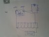
Sorrryy for such a messed up drawing. But my diagram was something like this :/ is it ok?
but do those look ok?Nice idea you got there, basically the same but you don't use alternator, you move the coil itself so that emf can be induced in that.
Here's what i drew.
And I am pretty sure that frequency was the independent variable and current was the dependent variable.
I also did the same as u did. I kept number of turns of coil and current in the circuit constant.I kept the no. of turns in the coil and the current from the power supply constant and used a variable frequency generator to vary the frequency.
signal generaot is also a correct approach of varying frequency of current as written in mark scheme of oct nov 2010 p52didnt we have to use type of signal generator ?
signal generat
signal generaot is also a correct approach of varying frequency of current as written in mark scheme of oct nov 2010 p52
I also did the same as u did. I kept number of turns of coil and current in the circuit constant.
I then measured resistance of coil by ohmmeter and Vo by CRO. and then calculated Io by V=IR. Is this correct??? plzzz reply thanx
exactly !so it wont be considered wrong?
Em still confusef that either Vo was to be copnstant or current???Congratulations. You're right.
Em still confusef that either Vo was to be copnstant or current???
secondly, how u cud say with surety that i am right....my most of the friends kept Vo constant....so em really cnfused atlarge!
Okay guys, here what i did for the design question.
I used a frequency oscillator to oscillate the coil, put two electromagnets on the sides. Emf induced or current induced was recorded on the CRO. Frequency was varied and the current was recorded.
For almost 10 years, the site XtremePapers has been trying very hard to serve its users.
However, we are now struggling to cover its operational costs due to unforeseen circumstances. If we helped you in any way, kindly contribute and be the part of this effort. No act of kindness, no matter how small, is ever wasted.
Click here to Donate Now